Operation
Technical Specifications
| Outputs | 8 relay |
| Voltage category | AC/DC normally open relay contacts |
| Operating voltage range | 5 - 277 VAC / 5 - 125 VDC |
| Max Current per channel | 5 A @ 250 VAC / 5 A @ 30 VDC ( resistive ) 2 A @ 250 VAC / 2 A @ 30 VDC ( inductive ) |
| Max Current per common | 10 A |
| Commons | 2 ( 4 CH / COM ) |
| Voltage and load type | Relay life |
|---|---|
| 5 A at 250 VAC ( resistive ) | 100,000 cycles |
| 5 A at 30 VDC ( resistive ) | 100,000 cycles |
| 2 A at 250 VAC ( inductive ) | 200,000 cycles |
| 2 A at 30 VDC ( inductive ) | 200,000 cycles |
Equivalent Schematic

Diagnostics
The Diagnostic view provides current and previous information for each digital output channel, helping identify wiring issues, sensor faults, and intermittent signal behavior.
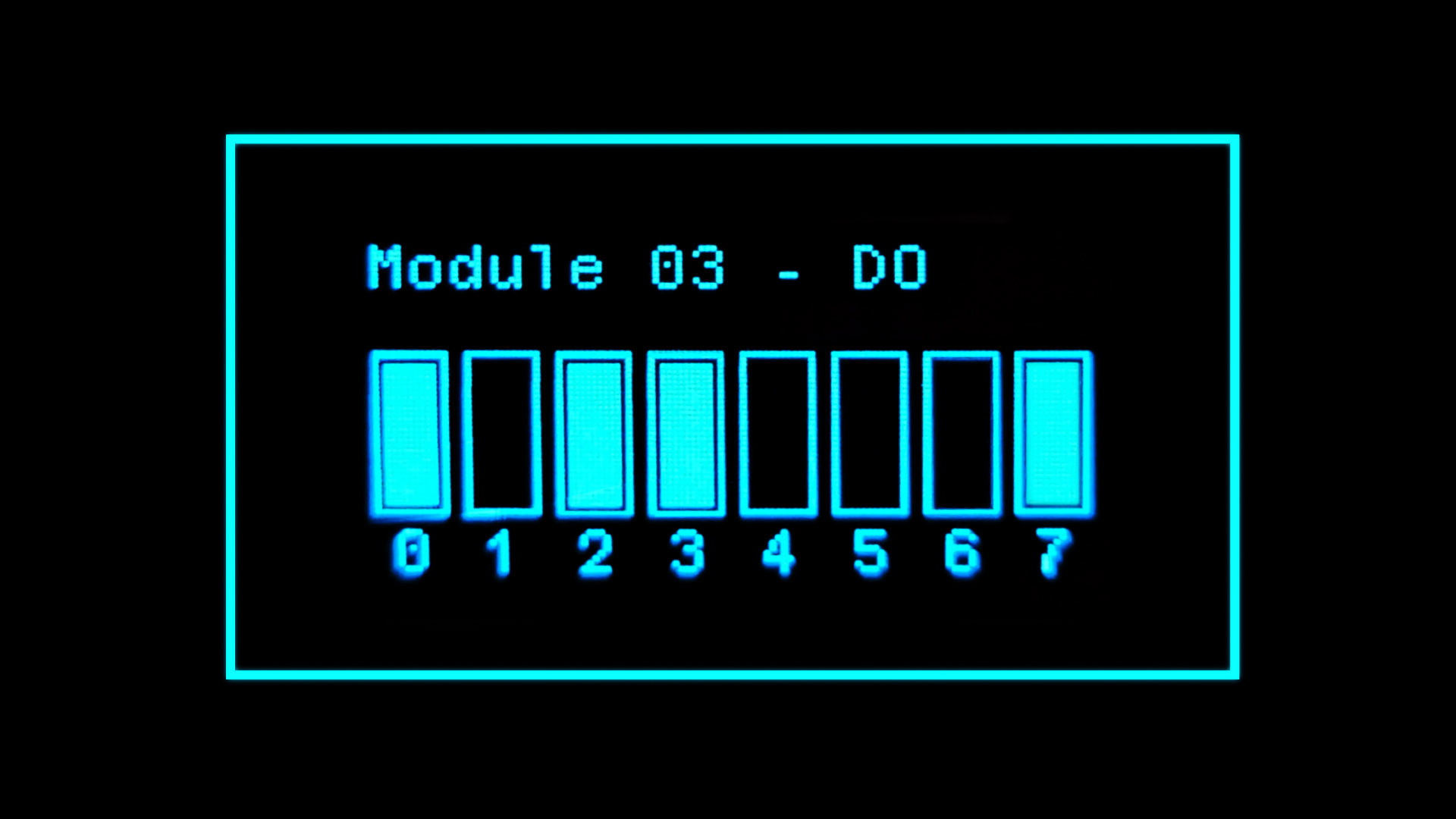
Channel Status Overview
The module displays the current state of all output channels, allowing quick verification of which outputs are active (ON) or inactive (OFF).
Per-Channel Diagnostic Details
Each output channel has a dedicated diagnostic page showing:
- Current Output State (ON / OFF)
- Most Recent State Change
- Date and time of the event
- State (ON/OFF)
- Previous State Change
- Date and time of the earlier transition
- Previous State (ON/OFF)
Module Information
The last diagnostic page includes a QR code linking directly to the module’s wiring diagram.